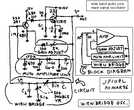
Sign wave audio generator for checking the audio amplifier
We must check the amplitude , frequency characteristic and maximum power of the audio amplifier , when we make a audio amplifier. For this purpose we need an audio generator. Let us make it by ourselves. I will show you the circuit of it. It will be easy for you to add a power supply or buffer amplifier for this circuit . See the block diagram! This is called as a Wien bridge oscillator. The frequency is changed by the double connected variable resister. The circuit made by C1, C2 and variable resister is a Wien bridge. When you connect this circuit between a input and output of the same phase amplifier , you can make the Wien bridge oscillator. But , If the amplitude is too big, The oscillated signal becomes the on-off pulse. If the amplitude is too small the oscillation can not begins. Therefore we must adjust the amplitude of it. You can see the "gain adjust" of this circuit. And when we turns the variable resister, the feedback ratio changes , and the shape of the wave changes. In order to keep the shape of the wave as the good sign wave , the amplitude is adjusted by the " auto amplitude limiter".
I like the FET called as 2SK241. It behaves as the remote-cutoff-pentode 6BA6. The gain of it is changed by the bias point. In this circuit, the DC voltage of the gate of FET is changed in order to change the amplitude of it. The next amplifier made by a transistor has about 20dB gain. This is a usual RC connected amplifier. The negative feedback is done from the collector of the transistor to the source of the FET. You must adjust the feedback ratio with seeing the oscilloscope in order to get a beautiful wave form. The FET amplifier has the 180 degree of difference of the phase between input and output of it. Also the transistor amplifier has the 180 degree of difference of the phase between input and output of it. Therefore the input of the FET and output of the transistor has 360 degree of difference of the phase. 360 degree means no difference. That means 0 degree.
The oscillated frequency of this circuit is calculated by this expression. f=1/(2*3.14*C*R). C=C1=C2. R=5.1k+50k*(1/n). n=0 to 1. The result of a experiment was as follows.
C1=C2-------f(Hz)of 5.1k ohm-----f(Hz)of 55.1k ohm
220p--------160k-----------------14k
0.0082u-----4k-------------------400
0.1u--------200------------------10
In order to get the beautiful wave form on all range, it is better to change the Rf resistor (5k ohms potensiometer) with the capacitor. You will need the 6 circuit of switch to this purpose. You can see very big numbers of the capacitor. In order to get the wide band amplifier , I must use the very big capacitors like 1000u. The original frequency of the "Auto amplitude limiter" must be low enough than the frequency of this oscillator. If the original frequency of the "Auto amplitude limiter" was near from the frequency of this oscillator, the intermittent oscillation happens. If the original frequency of the "Auto amplitude limiter" was smaller with the frequency of this oscillator, the oscillated signal becomes not good enough. You will be able to observe this phenomenon as the analog simulation of the feedback loop.

低周波増幅器の検査に欠かせない低周波広帯域発振器(汎用部品で構成した)
低周波増幅器を作った時には、一応増幅率や周波数特性や最大出力を計りましょう。この為には、正弦波の広帯域発振器が必要です。この機械を作って、ケースに入れておけば、重要な測定器になります。ここに示した回路の他に、電源回路や緩衝増幅器を付随させる事は容易な事でしょう。
ブロック図をご覧下さい。ここに示した発振器はウイーンブリッジ発振器といって、2連の50k可変抵抗によって発振周波数が変えられる低周波発振器です。回路図のC1、C2と2連の50k可変抵抗によって構成された部分がウイーンブリッジ(WIENBRIDGE)です。この回路を、同相増幅器の入出力につなげると正弦波が発生します。ただし、増幅器の利得が余り大きすぎると、矩形波になってしまいますし、反対に少なすぎると発振してくれません。このために、増幅器の利得は適当な大きさに調節する必要があります。負帰還によって、増幅器の利得を調節しているのが利得調節回路(GAINADJUST)です。さらに、ウイーンブリッジの可変抵抗をまわすと、微妙に利得が変化して、再度利得を調節しなくてはならないので、これを自動的に行ってくれて、出力振幅を一定に保ってくれるのが、自動振幅制限回路(AUTOAMPLITUDECONTROL)です。
2SK241は私が大変に好きな素子です。それは、真空管の6BA6と同じ様に、リモートカットオフ特性を示し、バイアスの変化によって、増幅率が調節出来ます。ここでは、ゲートの直流電圧を調節して、利得調節を行っています。
トランジスターの増幅器は極普通のCR結合増幅器です。20dBほど利得があります。
トランジスター増幅器からFETのソースに負帰還をかけています。ここは、出力波形をオシロスコープで観察しながら、適当なサイン波に成る様に、調節が必要です。
FET増幅器は反転増幅器で、入力信号と出力信号は、180度の位相ずれが有ります。トランジスター増幅器も反転増幅器で、入力信号と出力信号は、180度の位相ずれが有ります。それで、FETとトランジスター2段の増幅器は、全体で360度、すなわち同相増幅器になります。
ウイーンブリッジ発振器の発振周波数はf=1/(2πCR)です。ここでC=C1=C2。Rは50kの可変抵抗と5.1kの固定抵抗の和です。具体的に観察された、実験値としては、C=220Pで14kから160kHz。C=0.0082μで400Hzから4kHz。C=0.1μで10Hzから200Hz程度でした。
きれいな正弦波を得る為には、利得調節の5kオームの半固定抵抗もレンジ切り替えが必要です。6連のスイッチでC1,C2と半固定抵抗の3定数を切り替えると良い波形が広帯域にわたって発振できます。
この回路図を見て頂くと、普通のCR結合増幅器よりもパスコンの電解コンデンサーが10倍程度の値を使っている事に気が付かれるでしょう。これも広帯域化の為に必要な処置です。
自動利得調節回路の時定数は発振周波数に対して十分に低い周波数である必要が有ります。自動利得調節回路の時定数が発振周波数に近いと間欠発振になってしまいます。逆に自動利得調節回路の時定数が発振周波数に対して高いと波形が歪んでしまいます。これは、二重負帰還の原理的なアナログシミュレーションとして、工学的に重要な体験です。各部の電位の変化を2現象オシロで観察してみてください。(ちょっと難しい。すいません!)
back to index