vhfsg1.gif

VHF signal generator
vhfsg1.gif

I made a simple VHF signal generator in
order to measure the characteristic of low pass filter. The filter is made to
use on 50MHz SSB transceiver.
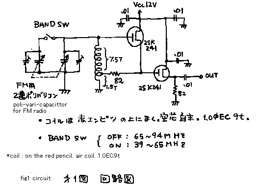
See fig1. Oscillator is normal HARTREY grounded drain with source follower.
See fig2. This figure indicates how to use it. I-ta is reducing ratio. Z is
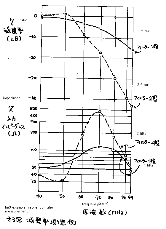
input-impedance. See fig3. This figure indicates the performance of the low
pass filter. Single filter has -15db ratio in 94MHz. Double filter has -45dB
performance. Each filter has very low loss on original 50MHz signal. Frequency
is measured by the counter. Gain is measured by the oscilloscope after
detection by 1N60 diode. I am confident of using these filters in my rig, after
measuring the character by this way.
From: Brian Keegan[SMTP:bkeegan@optusnet.com.au] Sent: Sunday, September
02, 2001 10:28 To: jf10zl@intio.or.jp Subject: Hello Hello Kazuhiro Sunamura,
Sorry to take so much time on your site, my hard drive crashed last month.As
I find your circuits and ideas very interesting for my own experimenting
in electronics and Ham radio, I had to come back and download them again.This
time stored on a ZIP disk. I have built the UHF and VHF generators and
am building up a Sweep Gen based on your circuit at present. 73"s
from Brian VK2TOX
VHF シグナルジェネレータ
50MHzのトランシーバーの送信出力に取り付けるローパスフィルターの特性を測るために,簡単な
VHF シグナルジェネレータを作りました。図1 をご覧下さい。発振回路は,普通のドレイン接地ハートレー発振器(というか、いわゆるECO発振器)とソースフォロワーです。図2をご覧下さい。この図は,この機械の使い方を示しています。η(イータ)は高調波減衰率です。Zは,入力インピーダンスです。図3
をご覧ください。この図は,本システムを使用して測定した、自作ローパスフィルターの性能曲線を示します。シングルフィルターでは94MHzで15dbの減衰量、2段フィルターでは45dBの減衰量性能でした。それぞれのフィルターは,基本波に相当する50MHzではとても低い損失を示しています。周波数は,カウンターで測りました。ゲインは,一度整流して、オシロスコープによって測りました。整流器の損失はここでは無視しています。減衰量の絶対値は問題ではありませんから、よしとしています。それでも、これで安心して,自作の50MHzSSB
リグにこの内臓のフィルター安心して使うことができるようになりました。
Fig2---vhfsg-2k.gif-----How to measure the reduced harmonics by the low
pass filter
Reduce ratio : n = 20 log ( Vc / Vb ) dB
Input impedance : Z = 47 * Vb / ( Va - Vb ) ohms
図2 : 本機の使い方:パイ型1段ローパスフィルターの特性測定の方法
高調波減衰率 : η = 20 log ( Vc / Vb ) dB
入力インピーダンス : Z = 47 * Vb / ( Va - Vb ) Ω

vhfsg-3

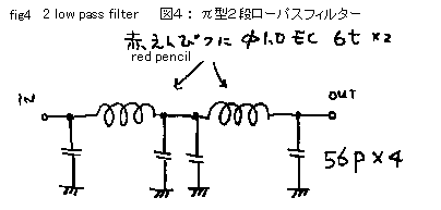
fig4---vhfsg4k.gif----pai type two stage low pass filter
図4 : π型2段ローパスフィルター

vhfsg5k.gif

Fig5 : How to make a case from a printed boad
1. Cut glass epoxi board by metal saw!
2. Bind panels by tape! Solder inside by 100W solder iron!
3. Solde nuts on its each sides! Take care not to solder screw!
4. Make four holes on the cover! The holes must be shaved to match the
location of nuts. Therefore holes becomes the long holes. You can see thir
shapes on the lower figure.
図5:プリント板ケースの作りかた
1.両面基板をカナノコで切って6面体を作る。
2.セロテープで箱の外側を仮付けしておいて、内側を100Wの半田ゴテで半田ずけする。
3.箱の内側4隅にM3のナットを半田ずけ。ナットが転がらない様にビスを付けておく。ビスまで半田を付けない様に。
4.蓋の4隅に穴をあける。当然の如く合わないので、現物あわせで、長穴にする。下の、実態図にも現れている。
vhfsg-6