 Experiment
of 1 transistor TV transmitter
Experiment
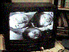
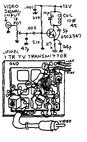
of 1 transistor TV transmitterI will show you a simple TV transmitter. But this is planned only for experiment. You can not make TV station with such a simple circuit. And experiment of this gear makes some interference for TV. I recommend you that you should make this experiment on the midnight. As you can see on the circuit, this is a VHF oscillator. The circuit of it is same as the oscillator on the TV convertor. Therefore you must use a transistor being sold to use for TV convertor. The ft of the transistor must be 650MHz or more. The video signal is put on the base of the oscillator. That makes a amplitude modulation. The video signal is generated by the video player or a digital camera. Of course a video camera can be used. Do not connect the antenna with this project! Connect the 10cm wire on the TV set on the same room as the antenna! The upper photograph shows the figure of received by the TV. Is it beautiful? My wife and my daughter and my third son. Is becomes a colorless as you can see. The oscillator of this transmitter acts as a base grounded. Therefore the base must be grounded by the capacitor "47pF". Therefore the color signal of the video signal is omitted(terminated). The coil of this oscillator is made by 1mm enamel wire. It is winded around the blue pencil. Four turn coil oscillates a signal for the 1 to 3 channel of TV. Two turn coil oscillates a signal for the 9 to 12 channel of TV. You must tune the trimmer capacitor by the bamboo driver. You must also tune the potentiometer in order to get a good modulation. The change of the Vcc makes a change of the frequency. Therefore you must use a regulated power supply. I think 10mA will be enough. You will be able to enjoy a electric home brew with this project. But , be care not to make TVI for your neighborhood!
tvtr.gif
 1石式テレビ送信機の実験
簡単なテレビ送信機を紹介します。あくまで、室内での実験用のものですから、くれぐれも電力増幅器を付けてテレビ放送を行ったり、屋外のビデオカメラから、自分の家のテレビに送信したりしようとなさらないでください。また、実験中は、本機の調整中に、ご近所のテレビに妨害を与える恐れがありますので、実験は、ご近所が寝静まってからされるのが良いと思います。回路は、見て頂いてお分かりの様に、VHFテレビの局発と同じ回路でテレビ電波と同じ周波数の信号を発生させて、これをベースから、ビデオ信号によって、いわゆる「ベース変調」させて、テレビの電波と同じ振幅変調をかけています。ここで使用するトランジスターは、VHFやUHF発振用として販売されている物でなければなりません。私の持っている東芝の1988年小信号トランジスターのデータブックには「テレビVHFチューナ周波数混合用」となっています。ftは最低650MHzとなっています。また、この回路の変調用のビデオ信号はお手持ちのAV機器のビデオ信号を入れてください。私はビデオテーププレーヤーから入れました。デジカメもOKです。もちろんビデオカメラもOKです。本機にはアン テナを付けずに、同じ部屋でテレビにアンテナ代わりの電線を10cm程度付けて受信します。上の画像はそれをまたデジカメで取ったものです。ちゃんと見えるでしょう。ただし、白黒になってしまっています。これは、本機の発振器がベース接地として動作しているためで、このため最低でも47pF程度でベースをアースに落とさないと発振してくれません。一方、このために、ベースから入力するヴィデオ信号の高周波成分が削り取られて、色変調信号が無くなってしまい、白黒画像しか送れていません。ここに、ヴィデオ増幅器をもう1段入れて低インピーダンスで駆動すれば良いのですが、まあ、やめて置きましょう。また、タンクコイルは、青鉛筆に1mm径のエナメル線を4回巻いた物です。これで、1から3チャンネルに同調できます。タンクコイルを2回巻きにすると9から12チャンネルに同調できました。タンクコイルと並列のトリマーコンデンサーを、竹串を削った物で回して、同調をとります。この時に明らかに、他のチャンネルの周波数も通ってしまうので、TVIを発生します。自分の合わせたテレビに縞模様が出たら、ポテンショを調節して、変調の深さを調節して、画像がき れいに見える様にしてください。この時、再度周波数も調整して。追い込んで行きましょう。本機は電源電圧の変動に対して、周波数も変わってしまうので、安定化電源を使用してください。電流は10mAもあれば十分です。電気工作は本当に楽しいですね、ただしくれぐれもご近所へのTVIには気を付けましょう。
back to index