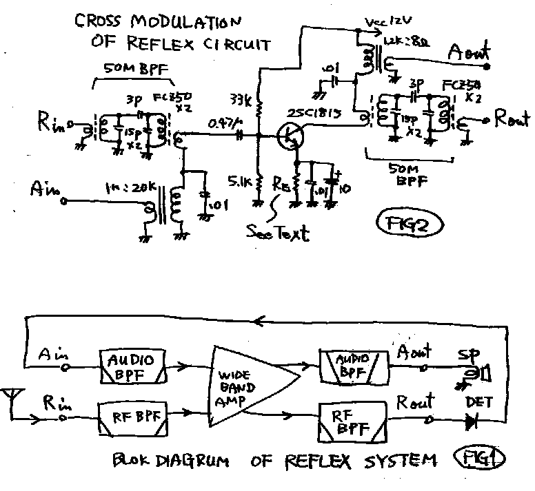
Sometimes, I use a reflex circuit in my products. In this page, reflex circuit means as follows. (See fig1!)
*Radio(Rf) signal is amplified by Rf AMP.
*Amplified radio signal is detected by diode detector.
*Detected audio(Af) signal is amplified by a audio AMP.
*One wide-band-AMP amplifies Af and Rf signal at the same time. Some kind of Af and Rf band-pass-filter is used on the input and output of wide-band-AMP. *****
I discovered that, the total gain of Af and Rf is smaller than the sum up of each gain. I considered and tested about the reason of it. ****
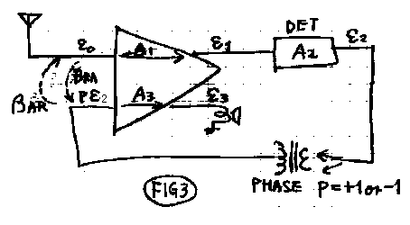
See fig3! In this figure, some words are decided.
A1: Gain of Rf AMP.
A2: Gain of detector.
A3: Gain of Af AMP.
A: Total gain of radio receiver.
eo: signal voltage of Rf in.
e1: signal voltage of Rf out.
e2: signal voltage of detector output.
p: phase between detector and Af AMP.
e3: signal voltage of Af out.
I want to show that.
A<A1+A2+A3
I consider that, the reason of it is "mutual interferance between
Af and Rf". Therefore I desided that.
Bar:interferance factor from Af to Rf.
Bra:interferance factor from Rf to Af.
Then the figure means that.
e1=(e0+p*e2*Bar)A1-------------(1)
e3=(pe2+e0*Bra)A3-------------(2)
e2=e1*A2----------------------(3)
A=e3/e0-----------------------(4)
(3)->(1)
e1=(e0+p*Bar*e1*A2)A1----------(5)
(3)->(2)
e3=(p*e1*A2+Bra*e0)A3----------(6)
from(5)
e1=e0*A1+p*Bar*e1*A1*A2
e1(1-p*Bar*A1*A2)=e0*A1
e1=(e0*A1)/(1-p*Bar*A1*A2)-----(7)
(7)->(6)
e3=[{p*e0*A1*A2/(1-p*BarA1*A2)}+Bra*e0]A3----(8)
(8)->(4)
A=[{A1*A2/(1-p*Bar*A1*A2)}+Bra]A3-----(9)
(9) means as follows.
1...Bra->0,Bar->0, then A=A1A2A3
If the cross modulation reduces, the total gain becomes the simple sum
up.
2...A>Bra*A3
If the cross modulation becomes very big, all the Rf gain becomes senseless.
Then only Bra*A3 becomes total gain.We sometimes make such a refrex.
3...In worst case total gain becomes zero.
In (9),set A=0.
A1A2/(1-p*BarA1*A2)=Bra---------(10)
set 1<<p*BarA1*A2<< p*BarA1*A2,so 1-p*BarA1*A2=p*BarA1*A2---(11)
(11)->
1-p*BarA1*A2=p*Bar*A1*A2-----(11)
(11)->(12)
Bra*Bar=1 or -1 ------------------(12)
e1=(e0+p*Bar*e1*A2)A1----------(5)
1-p*BarA1*A2=p*Bar*A1*A2-----(11)
たとえば Bra=2, Bar=0.5 なら総合利得は無くなる. ********
(bacause P=+1 or -1, 1/p=p)
for example Bra=2, Bar=0.5 then total gain is zero. ********
I made the circuit of fig2. I tested about some Re(emitter resister).
The best Re was 68 ohm.
A1=15,A2=0.5,A3=10,Bra=0.03,Bar=0.03,P=1,then culculated A=63,measuredA=50....
A1=37.5,A2=0.5,A3=35.0,Bra=0.0716,Bar=0.0050,P=-1,then culculated A=-95,measuredA=-125....
*********
when Re was 1.5kohm. When,A1=20,A2=0.5,A3=1.5,Bra=3.7(big!!),Bar=0.5,P=1,then
culculated A=15,measuredA=15...
. When,A1=20,A2=0.5,A3=1.5,Bra=3.7,Bar=0.5,P=-1,then culculated A=2.5,measuredA=1....
refrex1.gif

refrex2.gif

レフレックス回路についての熟考,および実験..
時々,私は,私の製品でレフレックス回路を使います.このページでは,レフレックス回路は,以下の物を意味します.
( fig1 を見て下さい! )
* 無線周波シグナルが,高周波(Rf)アンプによって拡大されます.
* 拡大されたラジオシグナルは,ダイオード検波器によって検波されます.
* 検波されたオーディオ( Af ) シグナルは,オーディオアンプによって増幅されます.
* 広い- バンド- アンプは,Af とRfを同時に増幅します.何らかのAf ,およびRf
バンド- パス- フィルターは,広い- バンド- アンプのインプット,および出力で使われます.
*****
私は,Af ,およびRf の全体のゲインが,それぞれのゲインの計算上の合計より小さくなる事を発見しました.私は,それの理由について熟考して,テストしました.
fig3をみてください! この図で下記の用語が定義されます。.
A1: Rf AMPの利得(倍、dBではない).
A2: 検波器の利得.
A3: Af AMPの利得.
A: ラジオ受信機の全体の利得.
eo: Rf 入力の電圧.
e1: Rf 出力の電圧.
e2: 検波出力の電圧.
p: 検波器とAf 増幅器の間の位相.
e3: Af 出力の電圧.
ここで私が証明したい命題は. A<A1*A2*A3です。
この理由は、”内部今変調である”と考え、これに関して、下記にファクターを定義しました。
Bar:Afから Rfへの影響係数.
Bra:Rfから Afはの影響係数.
ここで、図より.
e1=(e0+p*e2*Bar)A1-------------(1)
e3=(pe2+e0*Bra)A3-------------(2)
e2=e1*A2----------------------(3)
A=e3/e0-----------------------(4)
(3)->(1)
(3)->(2)
e3=(p*e1*A2+Bra*e0)A3----------(6)
from(5)
e1=e0*A1+p*Bar*e1*A1*A2
e1(1-p*Bar*A1*A2)=e0*A1
e1=(e0*A1)/(1-p*Bar*A1*A2)-----(7)
(7)->(6)
e3=[{p*e0*A1*A2/(1-p*BarA1*A2)}+Bra*e0]A3----(8)
(8)->(4)
A=[{A1*A2/(1-p*Bar*A1*A2)}+Bra]A3-----(9)
(bacause P=+1 or -1, 1/p=p) *****
(9) 式が回答ですこれより下記3点が分かりました.
1...Bra->0,Bar->0, なら A=A1A2A3
もし、相互干渉が十分に小さければ総合利得は各利得の合計である。
2...A>Bra*A3 もし、相互干渉が十分に大きければ総合利得はBra*A3である。
すなはち、低周波利得だけが残った状態。我々が作るレフレクスはしばしばこんな物です。
3...最悪、下記の条件では総合利得は無くなる.
(9)式で A=0とおいて.
A1A2/(1-p*BarA1*A2)=Bra---------(10)
ここで、一般に 1<<p*BarA1*A2だから<< p*BarA1*A2だから,
1-p*BarA1*A2=p*BarA1*A2---(11)
(11)->
(11)->(12)
Bra*Bar=1 or -1 ------------------(12)
fig2の回路を作ってみました. Re(エミッタ抵抗)をいろいろ変えて試験しました.最も良いReは68オームでした.この時、
A1=15,A2=0.5,A3=10,Bra=0.03,Bar=0.03,P=1,だったので計算上の総合利得はA=63,測定された利得はA=50....
*********
Re が1.5kohmのときには. A1=20,A2=0.5,A3=1.5,Bra=3.7(おおきい!!),Bar=0.5,P=1,計算上の総合利得はA=2.5,測定された利得はA=1でした...