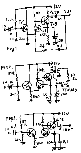
See Fig1! I feels that this circuit is very beautiful. Transistor 1 works as a collector grounded. Transistor 2works as a base grounded. Transistor 3 works as a emitter grounded. Transistor 1 works in order to keep a input impedance about 10k ohm. Transistor 2 works to separate the input from output . Transistor 3 works as an amplifier. All three transistors have the different jobs. This circuit is a sum up of merit of each types of circuits.
I discovered this circuit on the book. I bought the book in Muenchen on 1994. The name of the book is 300 circuits"300 Schaltungen".I made three types of this circuit. All the circuit is made by the transistor named 2SC1815.
Fig1 indicates the audio amplifier. Unless Rf (feedback resister), the gain of it was 78dB. With Rf=10k ohm, The gain was 46dB. With Rf= 1.5Kohm the gain was 34dB. This is tested by the 1kHz audio signal.
Fig2 indicates the head phone AMP. The voltage gain of it is 43dB. The noise of this circuit if too small for me to hear.
Fig3 indicates a HF amplifier. I tested the frequency characteristics of this circuit. With 455kHz the gain of it was 46dB. With 1MHz the gain of it was 41dB. With 3.3MHz the gain of it was 32dB. With 10MHz the gain of it was 20dB.
These circuits are very high gain. These circuits are very safety from self oscillation. I want to use them on my next project. Please make some kind of radio or transceiver with it and teach me the result!
Fig1 を見て下さい! この差動増幅器をとても美しい回路と思います.トランジスター1 は,コレクター接地として働きます.トランジスター2 は,ベース接地として働きます.トランジスター3 は,エミッター接地として働きます.トランジスター1 は,インプットインピーダンスをおよそ10k オームに保つために,働きます.トランジスター2 は,入力を出力から分離するために,働きます.トランジスター3 は,増幅器として働きます.3個のトランジスターは,それぞれ異なる目的を持っています.この回路は,それぞれの接地方式の足しあわせ回路です。
私は,本でこのサーキットを発見しました.私は,1994年にミュンヘンに行ったときにその本を買いました.本の名前は," 300回路"です.すべてのサーキットは,2SC1815 トランジスターによって作られています.
Fig1 は,オーディオの増幅器を示します.Rf ( フィード・バック抵抗)無しでは ,それのゲインは78dB です.Rf = 10k オームで,ゲインは,46dB でした.Rf = 1.5Kオームで,ゲインは,34dB でした.これは,1kHz オーディオ信号での結果です。.
Fig2 は,ヘッドフォンアンプを示します.それの電圧ゲインは,43dB です.この回路のノイズはとても小さいので、わたしには聞こえませんでした.< BR >< BR >
Fig3 は,高周波増幅器を示します.私は,このサーキットの周波数特性をテストしました.455kHz で,それのゲインは,46dB でした.1MHz で,それのゲインは,41dB でした.3.3MHz で,それのゲインは,32dB でした.10MHz で,それのゲインは,20dBでした。
これらの回路は,とても高いゲインです.これらのサーキットは,発振し難いので、非常に安全です.私は,次の作品それを使ってみたいと思います.あなたも、何かのラジオ,あるいはトランシーバーをそれで作って,私に結果を教えて下さい! そしてこのページの下に紹介させてください。できれば。。
back to index