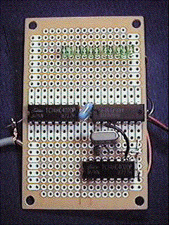
Simple Frequency Counter using 74HC4020....counterph.gif
1. Forward 74HC4020 is a 12-stage binary ripple counter IC. The maximum
frequency of it is 65MHz. About detail, please see the data book from the
IC maker! In this page , I made and show you the simple frequency counter.
It will cost only 7 dollars. This frequency counter circuit is good for
studying the basic principle of the frequency counter. And also it is good
to make the digital frequency indicating receiver by yourself. But this
gear indicates the frequency not with decimal but with binary. Therefore
to know the frequency you need to exchange the decimal to binary. But you
must have the computer to read my home page. HIHI
counter1.gif
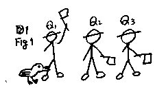
2. What is counter IC? See Fig1!
(1) A chicken pecks the leg of the Q1 man. Then Q1 ups the flag of his
left hand. " The figure shows this timing."
(2) On the next time, the chicken pecks the leg of the Q1 man again. Then
Q1 downs the flag of his left hand. And then, while he downs the flag,
he hits the helmet of Q2. Then Q2 ups the flag of his left hand.
(3) On the next time, the chicken pecks the leg of the Q1 man again. Then
Q1 ups the flag of his left hand. And then, Q2 holds the flag of his left
hand upside.
(4) On the next time, the chicken pecks the leg of the Q1 man again. Then
Q1 downs the flag of his left hand. And then, while he downs the flag,
he hits the helmet of Q2. Then Q2 downs the flag of his left hand. And
then, while he downs the flag, he hits the helmet of Q3. Then Q3 ups the
flag of his left hand.
I put these action of the men in order as follows.
"0"indicates the flag of each man holded on downside.
"1"indicates the flag of each man holded on upside.
| How many times the chicken pecks the leg of Mr.Q1? |
Flag of Q3 |
Flag of Q2 |
Flag of Q1 |
| 0 |
0 |
0 |
0 |
| 1 |
0 |
0 |
1 |
| 2 |
0 |
1 |
|
| 3 |
0 |
1 |
1 |
| 4 |
1 |
0 |
0 |
0 of decimal is 000 of binary.
1 of decimal is 001 of binary.
2 of decimal is 010 of binary.
3 of decimal is 011 of binary.
4 of decimal is 100 of binary.
The state of the flags indicates the times of the pecking of the chicken
with decimal. This is the basic theory of the counter. With the IC 74HC4020,
the count input is equal to the pecking of the chicken. Q1 output is equal
to the flag of Mr.Q1. But this IC is slightly strange. It lacks the Q2
and Q3 output. The flags of Mr.Q2 and Mr.Q3 will be broken. But they has
bar instead of the flags. They can translate the signals. But they can
not indicated the situation. If you try to make the counter , please make
with 74HC4040 instead of 74HC4020! 74HC4040 can indicates the all Q1 to
Q12. Sorry!
counter2.gif
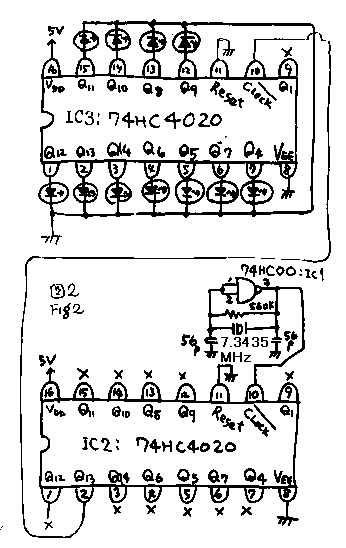
3. Use 74HC4020! Please make circuit like Fig2! (1)Make Crystal oscillator
with 74HC00! When you connect the two input terminals of the NAND-GATE
, it becomes the inverter. Connecting the resister between the input and
the output of the inverter, it becomes the linear amplifier by the negative
feed back. Connecting the crystal between the input and the output of the
amplifier, it becomes the crystal oscillator. Please check the frequency
of this oscillator with the oscilloscope! If it acts as an overtone oscillator,
please adjust the capacitor connected on the crystal! You can use any frequency
of the crystal for this circuit from 5Mhz to 12MHz. I used the crystal
named 7.3435Mhz from the junk box.
(2)Pouring this oscillated signal on the clock input terminal of the IC2
74HC4020, 13 times divided signal comes on the Q13 of this IS. 2 multiplied
13 times is 8192. Therefore the signal of Q13 becomes 7.3435M / 8192 =
896.4233 Hz.
(3) Pouring this 896.4233Hz signal on the clock input of the IC3 (74HC4020)
, then the signal coming on the Q13 terminal of the IC3 becomes 8192 times
slower signal than 896.4233Hz. It becomes 0.109Hz. Therefore the LED connected
on the Q13 of IC3 twinkles one time by the 10 seconds. Q14 twinkles one
time by the 20 seconds. Q12 twinkles one time by the 5 seconds. You can
look how the signal is transported between Q12 ,Q13 and Q14. It will be
very good experience to understanding the counter. Line the LED*s up like
Q4,Q5,Q6,Q7,,,Q13,Q14! Not line the LED*s up like Q12,Q13,Q14,Q6,Q5,Q7,,,because
of the arrangement if the terminal of 74HC4020!
counter3.gif
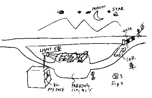
4. Basic theory of the frequency counter. Metaphor: How many traffic on
the high way in the dark?
(1)Ten minutes of each one hour, close the gate of the pass through of
the high way! And guide the cars to the parking! Arrange the cars on the
parking area! I stands on the second floor of the lunch house. While the
cars coming to the parking , I turn off the switch of the light not to
look the cars coming.
(2)After ten minutes, open the gate to pass the cars of the through traffic!
Turn on the light of the parking! Then I can know the number of the car
on the parking. The hole number of the car pass through the traffic is
six times of the cars of the parking.
(3)Turn off the light on the roof of the lunch house! Return the cars on
the parking to the through traffic! Lacking of this work, the cars of this
hour and next hour will be mixed.
The work (1) is called as count.
The work (2) is called as indicate.
The work (3) is called as reset.
counter4.gif
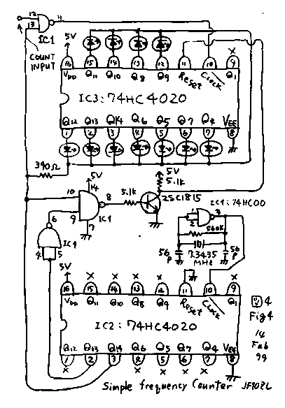
5. All circuit
See fig4! This is the all circuit of this gear. IC3 is the counter as the
center of this gear. All another parts of this gear work as a timing control
block to make command of (1) count , (2) indicate and (3) reset. I will
explain how these three command are made with this circuit.
counter5.gif

(1) How the " indicate" command is made.
About the crystal oscillator and the divider of IC2, the circuit of fig4
is the same as fig2. Therefore as I explained already, on the Q13 terminal
of IC2, coming the 896.4233Hz ON-OFF signal. And on the Q14 terminal of
IC2, coming the 448.21165Hz ON-OFF signal. I disconnect the ground connection
of the resister of the LED's of IC3. And I connect it to the Q14 of IC2.
When this terminal is low level, the LED's can twinkle following the level
of the Q terminals of IC3. When this terminal is high level, the LED*s
can not twinkle with no concern of the level of the Q terminals of IC3.
Therefore Q14 commands the indicating time with it's low level.
counter6.gif
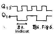
(2) How the " reset" command is made. As the next command , while
Q14 is high timing, the reset and count commands must be made. Only with
the signal of Q14, this two command can not be made. Therefore I had to
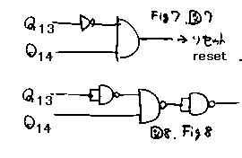
get the help of the Q13 of IC2. While Q13 is low and Q14 is high timing,
I had to make reset command. For this purpose I constructed the circuit
of fig 7. And Fig.7 is constructed with three NAND-Gate*s like fig.8.
counter78.gif
counter9.gif

(3) How the "count" command is made.
I had to make the count command while Q13 is high and Q14 is also high
level like (1) timing of fig.9. But I could use the Q14 signal as count
command. Because the reset command takes priority of count command with
it*s nature of the counter IC 74HC4020.
counter10.gif
 The
action of NAND-Gate
| #12 input |
L |
L |
H |
H |
| #13 input |
L |
H |
L |
H |
| #11 output |
H |
H |
H |
L |
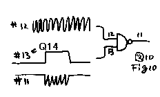
Count command is carried out by one unit of NAND-Gate. See fig.10! Pour
the measured signal on the terminal of #12! Pour the count command on the
#13 of the gate! By the action of NAND-Gate, while the #13 is low, #11
remains high with no concern if the state of #12. While #13 is high the
#11 becomes inverted situation of #12 input terminal.
6. I needed five NAND-Gate's.
Crystal oscillator needs a NAND-Gate. Reset commander needs three NAND-Gate*s.
Counter-Gate needs a NAND-Gate. Totally this circuit needs five NAND-Gate's.
But 74HC00 has four units on it. I substitute a inverter of the reset commander
with a transistor inverter.
7. The performance of this frequency counter.
Count time (Tc) is Q13. Q13 is 13 times divided from oscillator 7.3435MHz.
Therefore Q13 is 7.3435 M/8192=896.4233Hz. Tc is half cycle of Q13. So
Tc= (1/896.4233 )*0.5 = 0.557772msec. It is 1792Hz. Smallest readable frequency
is Q4. Q4 is 16 times of 1792Hz. Therefore smallest readable frequency
is 28.685kHz. Biggest readable frequency is Q14. Q14 is 16384 times of
1792Hz. Therefore biggest readable frequency is 29.4MHz.
8. Conformation of the work.
To confirm the work of this counter , I connected this gear to the 10.24MHz
crystal oscillator of the PLL radio. F : the frequency of the measured
signal. Tc : the counter time. N : the indicated number. N=f*Tc N=10.24*1000000*0.557772*0.001=5711
Please exchange this number for the 14 places decimal! It becomes 01011001001111.
This counter indicates Upper 11 places. It becomes 01011001001. The LED's
of this frequency counter indicated the same result. Good!
9. The cost of this gear.
I could get the parts of this gear in Japan.
Parts....................price.........amount
74HC00...............35Yen/@..........1
74HC4020...........95Yen/@.........2
2SC1815..............10Yen/@.........1
Crystal..................100Yen/@.......1
Board.....................90Yen/@.........1
LED.........................20Yen/@.......11
Total.......................650Yen
This frequency counter cost about 6 dollar with the Yen - Dollar rate of
18 Feb 1999.
10. Homework from me.
(1) Use 74HC4040! This IC can indicate full of 12 places.
(2) Use two 74HC4040 as the counter series! With 24 places LED*s , you
can construct a counter having a smallest readability of 3Hz.
(3) Instead of 74HC00 , use 74HC02! You may construct simpler command generator.
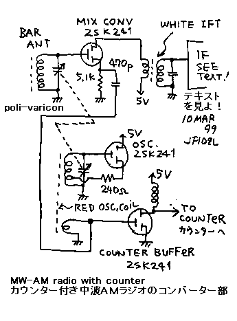
11. I installed this frequency counter in my small receiver. I could make
a digital frequency Radio. Counter is the same with upper diagram. Radio
block is based on the "simple four stage FET radio number 108 of my
home page". But in order to make strong oscillator , oscillator is
made independently. Oscillator coil is a normal red coil of the 6 transistor
super radio. Output voltage of the oscillator is 400mV peak to peak. I
set the simple wide band amplifier between the oscillator and the counter.
All this gear is operated with 5V Vcc. IF frequency is 455kHz. Therefore
oscillator frequency is receiving frequency plus 455kHz. Count number is
the oscillator frequency divided by 1792Hz. To exchange this number to
2 places , I got the counter number. The lower three places are not indicated
by LED. When I turn the variable capacitor, I enjoyed the twinkle of the
LED. I can know the receiving radio station with these LED's as follows.
| Name of station |
Radio frequency (f)kHz |
oscillator frequency (f+455)kHz |
count number (N) |
2 places of (N) |
Tokyo broadcasting
station |
954 |
1409 |
786 |
1100010-010 |
| Bunka Housou |
1134 |
1589 |
887 |
1101110-111 |
| NIPPON HOUSOU |
1242 |
1697 |
947 |
1110110-011 |
| Ibaraki broadcast (Mito city) |
1197 |
1652 |
922 |
1110011-010 |
| Ibaraki broadcast (Tsuchiura city) |
1458 |
1913 |
1068 |
10000101-100 |
counter11.gif
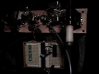
counter12.gif---This photograph indicates count number " 1010011".
(74HC4020を2個使った)簡単な周波数カウンター....counterph.gif

1.前書き
74HC4020は14ーSTAGE BINARY RIPPLE COUNTERです。これは、16ピンパッケージの中に最大クロック周波数65MHzという高速のカウンターを14個直列に入れたICです。詳細は、各社のCMOSデジタルICの規格表をご覧ください。今回はこのIC2個と、NANDゲートの74HC00を1個使って、1000円でおつりが来る値段で、周波数カウンターを作ってみました。
周波数カウンターの基本を勉強するのに好適です。また、これで、ラジオ受信機の局部発振周波数をはかれば、デジタル式周波数直接読み取りラジオが構成できます。但し、表示が完全な2進数なので、10進から2進数への変換計算が必要です。
counter1.gif

2.カウンターICとは何か
図1を見てください。
①:鶏(ニワトリ)が、Q1君の足をつつきます。すると、Q1君は旗を上げます。(図1はこの状態を示しています。)
②:次に、もう一度、鶏が、Q1君の足をつつきます。すると、Q1君は旗を下げます。そして、この時、Q1君は旗を下げながら、旗の棒で、Q2君のヘルメットをはたきます。すると、Q2君は旗を上げます。
③:次に、もう1度、鶏が、Q1君の足をつつきます。すると、Q1君は旗を上げます。この時Q2君は旗を上げたままです。
④:次に、もう1度、鶏が、Q1君の足をつつきます。すると、Q1君は旗を下げます。そして、この時、Q1君は旗を下げながら、旗の棒で、Q2君のヘルメットをはたきます。すると、Q2君は上げていた旗を下げます。そして、Q2君も旗を下げながら、旗の棒で、こんどはQ3君のヘルメットをはたきます。すると、Q3君が今度は旗を上げます。
以上を整理したのが、下の表1。です。
表1:”0”は旗が下がった状態、”1”は旗が上がった状態を示す。
| 鶏がQ1君の足をつついた回数 |
Q1君の旗 |
Q2君の旗 |
Q3君の旗 |
| 0 |
0 |
0 |
0 |
| 1 |
1 |
0 |
0 |
| 2 |
0 |
1 |
0 |
| 3 |
1 |
1 |
0 |
| 4 |
0 |
0 |
1 |
さて、ここで、Q1,Q2,Q3をQ3,Q2,Q1と並べ直してみると、
鶏がQ1君の足をつついた回数=”0”の所のQ3,Q2,Q1=000は2進数の”0”ですし、
鶏がQ1君の足をつついた回数=”1”の所のQ3,Q2,Q1=001は2進数の”1”ですし、
鶏がQ1君の足をつついた回数=”2”の所のQ3,Q2,Q1=010は2進数の”2”ですし、
鶏がQ1君の足をつついた回数=”3”の所のQ3,Q2,Q1=011は2進数の”3”ですし、
鶏がQ1君の足をつついた回数=”4”の所のQ3,Q2,Q1=100は2進数の”4”になっています。
つまり、旗の上げ下げの状態は、それまでに、鶏がQ1君の足をつついた回数を数えて、表わしている、というわけです。
これが、カウンターICの基本原理です。4020というICにおいては、カウント入力が、上の例の鶏に相当します。また、Q1,Q2,Q3君達の旗がQ1,Q2,Q3の出力端子に相当します。但し、4020というICはちょっとかわっていて、1つのICチップの中にQ1からQ14までの14のヘルメットをかぶった、人達がいるのですが、その中の、Q2君とQ3君の旗は、昔両名があまりにも激しく旗をふった為に、ちぎれ飛んでしまっていて、棒だけになっています。それで、Q2、Q3の両名は信号を伝達はできるのですが、その状態は外からは見えなくなっています。
4020の仲間で4040というICもあり、これは12段すべてのカウンターの出力がみえるので、もっと話は単純です。あなたが、同じ製作をされるなら、4040または74HC4040でやってみてください。あくまで、私の手持ちの部品の都合です。ごめんなさい。
counter2.gif
 3.74HC4020を組んでみる。
ここまで、来たら、図2の様に回路を組んでみましょう。
①:IC1(74HC00)で水晶発振器を組んでください。74HC00はナンドゲートですが、1番端子と2番端子の二つの入力をつないでしまうと、ただのインバーター(反転器)になります。このインバーターの入力と出力を560kオームの抵抗でつなぐと、負帰還が働いて、高増幅率のリニアー増幅器に似た動作をします。この入出力の間に水晶を入れると発振器ができます。始め、水晶の両端のコンデンサーを21pFでやったら、3倍オーバートーンで発振しました。出力端子にオッシロスコープをあてて基本波発振が得られている事を確認してください。そうでなければ、コンデンサーを加減してください。水晶は5MHzから12MHzまでなら、なんでもOKです。切りの良い周波数である必要は全くありません。その理由はあとでわかります。ここでは、私のジャンク箱の中から7.3435MHzを使いました。
②:さて、この発振信号を、IC2のカウンターに入れると、Q13には13分周された波形が出てきます。つまり、この周波数は7.3435MHZの周波数に対して、2の13乗分の1=8192分の1、の周波数ですから、(7.3435M/8192)=896.4233Hzの矩形はです。これでもまだ人間にとっては、高い周波数です。
③:この896.4233Hzの信号を、さらにIC3のクロックにぶち込みます。そして、IC3のQ13では、さらにこの8192分の1の周波数、つまり0.109Hzになります。つまり大体10秒に1回の周期です。ですから、このQ13にLEDをつなげると、そのLEDは10秒に1回点滅します。これなら十分に目でみてわかるという訳です。同様に、Q14では20秒に1回点滅します。また、同様に、Q12では5秒に1回点滅します。そして、Q12、Q13、Q14と信号が伝達されて行く様子がよくわかり、カウンターICの理解に役立ちます。また、IC3につなげる、LEDは、ICの端子配列の様にQ12,Q13,Q14,Q6,Q5,Q7という順番ではなくて、Q4,Q5,Q6,,,Q11,Q12,Q13,Q14と並べてください。この実験は、LEDの並べかたが正しい配線になっているかの確認にもなります。(もちろん、あなたが4040を使ったら、配線は変えてください。)さて、こうやってカウンターICに信号をいれてLEDをぱちぱち点滅させているだけでは、周波数は定量的にはわかりません。
次に、どうやってこのICで周波数を計るかを、たとえ話で、説明しましょう。
counter3.gif
 4.カウンターの原理説明(たとえ話)
夜の高速道路の交通量を計る例をたとえ話にして、カウンターの原理説明をします。図3を見てください。
①:1時間のうち最初の10分だけ、本線のゲートを閉じて、車をパーキングエリアに導いて、そこで、順番に整列させます。この時、私はパーキングエリアの見下ろせる食堂の二階に居るとします。車を導入している間は、車の動きがちらちらするだけなので、あえて照明灯は消しておき、車を見ない様にする事にしましす。
②:そして、10分たったら、ゲートを本線に対して開放し、逆に車がパーキングに来ない様にします。そこで、パーキングエリアの照明灯を付けると、とたんに車の数がはっきりします。そして、この車の台数は10分あたりの数なので、1時間あたりではこの6倍の交通量が本線にあると計算されます。
③:最後に、パーキングにたまった車を、本線に戻してやります。こうしないと、次にまた車をパーキングにいれて1時間後の交通量を計ろうとした時に、さっきの台数と混ざってこんがらがってしまいます。そして、この時は、また、照明を消して、車の流れをあえて見ない様にします。
①の作業がカウント(計数)
②の作業がインディケート(表示)
③の作業がリセット(ゼロ戻し)
と呼ばれます。
counter4.gif

5.周波数カウンターの全回路図
さて、ずいぶんと前置きが長くなってしまいました。図4が今回の製作の回路図です。IC3がカウンター本体のICです。それ以外の回路は全て、このカウンター本体に①カウント②インディケート③リセットの命令を与えるためのタイミングコントロール回路(時間制御回路)です。さて、この3つの命令信号を作る為には少し工夫が必要です。それに関して説明します。但し、説明の都合で②のインディケート(表示)から説明します。
counter5.gif

①:表示制御信号の作成
IC1の水晶発振器の部分と、IC2の分周期の部分に関しては、図4も図2も同じ結線です。ですから、IC2のQ13には896.4233Hzの矩形波が出てくる事に関しては、すでに3の②で説明しました。また、Q14にはその半分の周波数の448.21165Hzが出て来る事はご理解頂けるでしょう。IC3のカウンターのLEDのカソードの接地をはずして、このIC2の14番端子につなげてやると、この14番端子がローレベル(0ボルト)の時にはLEDは表示可能となり、IC3のQ4からQ14までの信号を表示できる状態になります。また、この14番端子がハイレベル(5ボルト)の時にはLEDは表示不可能となり、IC3のQ4からQ14までの信号のいかんに関わらず、LEDは点灯できません。よって、Q14がローレベルの時に、表示時間となります。
counter6gif
 ②:リセット信号の作成
次に、Q14がハイレベルである間に、リセットとカウントの動作を行わなくてはなりません。Q14の信号だけでは、2つの命令は出せないので、一つ前のQ13の信号にも協力してもらいます。図6に示した様に、Q13の立ち下がりのタイミングでQ14の状態が反転する様になっています。
よって、Q13がL(ロー)でかつQ14がH(ハイ)の時に、リセット命令を行い、Q13がH(ハイ)でかつQ14がH(ハイ)の時に、カウント命令を行えば良いという事が図6からわかります。
Q13がL(ロー)でかつQ14がH(ハイ)の時に、リセット命令を行うという事は、図7の様にゲートを組んでやれば良いわけです。そして、図7のアンドゲートは、図8の様にナンドゲート2つを使って構成できます。
counter78.gif

counter9.gif

③:カウント命令信号の作成:Q13がH(ハイ)でかつQ14がH(ハイ)の時に、カウント命令を行えば良いという事は、先ほど説明しました。すなはち、図9の①でしめした部分です。これもリセット信号と同等にナンドゲートを使って合成すれば良いのです。ただし、74HC4020というICの性質から、リセット命令とカウント命令が同時に入った場合は、リセット信号が優先します。(これは74HC4040を含めたほとんどすべてのカウンターICに共通の性質です。)従って、図9の②で示したタイミングに於いて、カウント命令を出しても、その前半に於いては、リセット命令が優先されるいので、カウントは行われず、結果は同じ事になります。よって、Q14がHレベルにおいてカウント命令をだします。
counter10.gif
 表2:NANDゲートの動作のおさらい
| 12番入力 |
L |
L |
H |
H |
| 13番入力 |
L |
H |
L |
H |
| 11番出力 |
H |
H |
H |
L |
カウント命令はIC1の74HC00の中の1つのユニットを使って実行できます。図10の様に、NAND(ナンド)ゲートの12番端子に、測定しようとする信号を入力します。また、NAND(ナンド)ゲートの13番端子には、IC2の14番端子の信号を入力します。すると、ナンドゲートは表2の如く動作するので、結果的に、NANDゲートの11番出力端子には、図10の如く、13番端子がH時だけ12番信号が(反転して)現れ出て来ます逆に、13番端子がLレベルの時には、12番の信号は11番出力端子に出て来ません。
6.ナンドゲートが5個必要!?
さて、以上説明してきた様に、NANDゲートが、水晶発振器に1個、リセット信号の合成に3個、カウンターゲートの構成に1個の合計5こ必要になりました。しかし、74HC00にはNANDゲートが4個しか入っていません。1個たりません。そこで、もう一つ74HC00を奮発してしまっても良いのですが、ここでは、図4に示した如く、リセット信号合成回路の内の一つの働きを、トランジスターで置き換えています。
7.このカウンターの性能
カウント時間をTcとすると、Tcは、7.3435MHzを13分周波した波形の半分ですから、
Tc=(1/7.3435*1000000)*8192/2=0.557772msecつまり1792Hz。
最小読み取り単位はQ4なので、2の4乗つまり16倍だから、28.685kHz。
最大読み取り単位はQ14なので、2の14乗つまり16384倍だから、29.4MHz。
8.動作確認
確認のために、PLL式短波ラジオの10.24MHz(fMHz)の水晶発振器の信号をいれてみました。10.24MHzの波形は、先ほど計算したカウントタイムTc=0.557772msecの何倍か(N倍)と計算すると、
N=f*Tc=10.24M*0.557772m=5711(少数以下切り捨て)
この5711を14桁の2進数で表現すると01011001001111です。
カウンターの出力はこのうち下3桁を切り捨てた数値ですから、01011001001となります。ちゃんとそのようにLEDが点灯しました。ちなみに、わたしのコンピューターはIBMのアプティバJ51という機種で、ウィンドーズのアクセサリに電卓機能があって、10進から2進数への変換は瞬時です。
9.この周波数カウンターのお値段
部品を列挙し、通信販売の価格を積算すると
74HC00............35yen/@*1
74HC4020.......95yen/@*2
2SC1815..........15yen/@*1
水晶.................100yen/@*1
基板...................90yen/@*1
LED...................20yen/@*11
合計.................650yen
あと電線や抵抗をふくめても1000円でお釣がきます。
10.私からの宿題
①74HC4040を使ってみましょう。フルに12桁表示できますから、2倍の分解能が2倍になります。
②74HC4040を、カウンターと基準信号発生にそれぞれ2個直列に使ってみましょう。分解能が24けたになって、最小分解能3Hzという驚異的な分解能が得られます。
③命令信号合成に74HC00(NAND−GATE)の代わりに74HC02(NOR−GATE)を使ってみましょう。少し簡単になるかもしれません。
11.カウント入力に広帯域増幅器を前置して、ちいさな信号もカウントできるようにして、中波の6石ラジオの局発信号を測定して、デジタルラジオに改造してみました。カウンター部分は、上の回路そのままです。ラジオの部分は別のページ(NO.108)のラジオがベースですが、局部発振器を強力にする為に、発振器を下図の如く、独立させました。発振コイルは6石スーパーに使われている赤い発振コイルそのままです。発振コイルの2次側の振幅は400mVピーク程度でしたので、1石の簡単な広帯域増幅器をいれて電源とアースいっぱいに振幅を増幅しました。電源は、ラジオもカウンターも両方5Vで動作させています。中間周波が455kHZなので、受信周波数に455kHzを足した周波数が局発周波数です。これを、カウンターの周期の1792Hzで割った数字がカウント数です。これを2進数になおして、さらに下3桁(下の表のーの後の3桁)を取った物が、LED表示になります。ポリバリコンを回すと面白い様にLEDが点滅して、周波数が表示されました。一発でTBSか文化放送かがわかります。
| 放送局名 |
受信周波数(f)kHz |
局発周波数(f+455)kHz |
カウント数(N) |
Nの2進数 |
| TBS |
954 |
1409 |
786 |
1100010-010 |
| 文化放送 |
1134 |
1589 |
887 |
1101110-111 |
| 日本放送 |
1242 |
1697 |
947 |
1110110-011 |
| 茨城放送(水戸) |
1197 |
1652 |
922 |
1110011-010 |
| 茨木放送(土浦) |
1458 |
1913 |
1068 |
10000101-100 |
counter11.gif

counter12.gif

写真は 周波数「1010011」を示す。
back to index


 The
action of NAND-Gate

