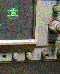
corpmarkph1.gif
 Corporate
mark generator : I remember to read the text that " we can look the
corporate mark of textronics company on the textronics oscilloscope by
inputting the pass word" on the Japanese CQ magazine. It must be made
with the remaining of the memory of the digital oscilloscope. In this page
I want to show you the similar one made with analogue process. I will explain
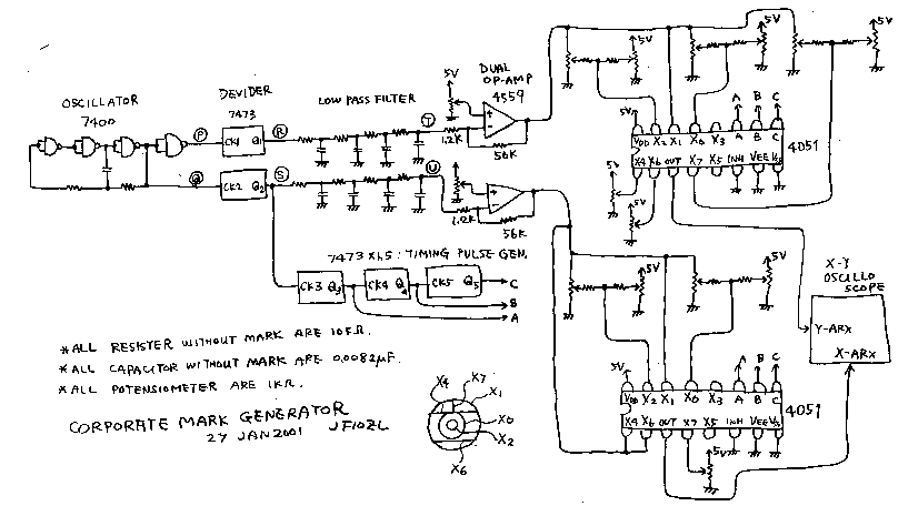
how it works by the circuit diagram. 7400 ,the left end of the drawing,
oscillate the pulse about 1kHz. P point and Q point has 180 degree different
phase. They are divided for half frequency wave by the JK flip -frop of
7473. The phase of the pulse wave on R and S points are different 90 degree
from each other. these waves are translated to sign wave by the low pass
filter. T and U are the 2Volts biased 100mVp-p sine wave. You can see the
circle form when you input the T and U point on the X and Y arcs on your
oscilloscope. But this wave is small and this circle is small. I made the
amplifier with the dual OP amp. By the way, pulse wave on the S point is
divided by anther tree JK flip -flop. This waves are used to the timing
pulse for the 4051 analogue multiplexer. Input of the multiplexer X1 is
used to pass the sine wave directly to the output, in order to draw the
big circle. X0 and X2 are used to draw smaller two circles by dividing
the sine wave. The vertical line is drawn by crushing the circle. I have
drawn the corporate mark of my company. You can draw the mark of Audi or
mark of Benz with the similar circuit. You may draw more complex line by
using difference and integral circuit. You may also draw half circle by
using Z arc (brightness arc of oscciloscope).
corpmark2.gif

コーポレートマークジェネレーター(商標発生装置):
もう何十年も前の事になりますが、CQ誌の記事の中に「テクトロのオッシロスコープでは、隠しコマンドを入力すると、画面にテクトロのコーポレートマークが現れる。」というのを読んだ記憶があります。これは、もちろんデジタルオシロで、メモリーの余分を使った遊びだとおもいます。今回は、これをアナログでやってみました。写真をごらんください。次に、回路図に従って、構成を説明します。尚、回路図で断わり無き抵抗は10kオーム、断わり無きコンデンサーは0.0082μF。ポテンシオメーターは全て1kオームです。電源は5Vのプラスだけの単電源です。最初に回路図の左端の7400で1kHz程度の矩形はを発振させます。最後のインバーターで反転しているので、(P)点と(Q)点は逆相になります。これをそれぞれ7473のデバイダーで1/2分周期すると、出てきた波形は、(R)と(S)店で90度位相の異なった波形が得られます。これをロ—パスフィルターに掛けると波形がサイン波になり、(T),(U)各点には90度位相の異なった、サイン波で2Vにバイアスされた振幅100mVp—pの波形が得られます。これをそのままオッシロスコープのXY
座標にいれてやると、1:1のリサージュ、すなわち丸い円形がオッシロスコープの表示に現れます。但しこのままでは、リサージュが小さいので、オペアンプで2Vp−pまで増幅してやります。さて、話は戻って、(S)点の波形を、さらに7473(デュアルJKフリップフロップ)を2個使って1/2、1/4、1/8と分周してやり、この波形をそれぞれA,B,C,と名付けて、アナログマルチプレクサーである4051のタイミングコントロール端子に入れてやります。すると、2つのアナログマルチプレクサーは、(S)点の1周期ごとに入力を切り替えて出力に伝えますので、X0からX7までの各入力端子に円形を縮小して同時に適当にバイアスをかけた信号をいれてやると、いろいろな大きさの同心円が現れます。あとは、同心円の縦方向をつぶせば水平な線が描けますし、同心円の横方向をつぶせば垂直な線が描けます。試しに、私が勤めている会社のマークを表示させてみました。ほとんど同じ回路でオリンピックマークやアウディーマークも描けます。また、日立マークには太陽のフレアが四方にのびているのですが、そこまでできていません。微積分回路を応用すれば細かいひげも
描けるでしょう。また、Z軸(明暗軸)に信号をいれれば、円の半分を消して半円を描いたりも可能です。ただし、この機械は暇つぶし以外の何の役にもたちませんので、ご注意ください。
back to index
 Corporate
mark generator : I remember to read the text that " we can look the
corporate mark of textronics company on the textronics oscilloscope by
inputting the pass word" on the Japanese CQ magazine. It must be made
with the remaining of the memory of the digital oscilloscope. In this page
I want to show you the similar one made with analogue process. I will explain
how it works by the circuit diagram. 7400 ,the left end of the drawing,
oscillate the pulse about 1kHz. P point and Q point has 180 degree different
phase. They are divided for half frequency wave by the JK flip -frop of
7473. The phase of the pulse wave on R and S points are different 90 degree
from each other. these waves are translated to sign wave by the low pass
filter. T and U are the 2Volts biased 100mVp-p sine wave. You can see the
circle form when you input the T and U point on the X and Y arcs on your
oscilloscope. But this wave is small and this circle is small. I made the
amplifier with the dual OP amp. By the way, pulse wave on the S point is
divided by anther tree JK flip -flop. This waves are used to the timing
pulse for the 4051 analogue multiplexer. Input of the multiplexer X1 is
used to pass the sine wave directly to the output, in order to draw the
big circle. X0 and X2 are used to draw smaller two circles by dividing
the sine wave. The vertical line is drawn by crushing the circle. I have
drawn the corporate mark of my company. You can draw the mark of Audi or
mark of Benz with the similar circuit. You may draw more complex line by
using difference and integral circuit. You may also draw half circle by
using Z arc (brightness arc of oscciloscope).
