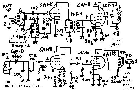
1. You know that 5 valve super heterodyne is made with line up by 6BE6-6BA6-6AV6-6AR5. But it is not fixed. You can use any type of valves for that purpose. In this project I used a pair of triode-pentode-combined valves.
2. Audio amplifier is constructed with normal circuit. Power amplifier is made by pentode. This pentode flows only 10mA. Therefore power output is about 100mw. But it is enough to hear with speaker. The gain of it was 8dB. Triode of 6AN8 is middle amplitude type. Therefore this amplifier has only 20dB gain. It is smaller than high myu (6AV6) triode.
3. In normal super heterodyne, pentode is used for IF amplifier. The pentode has small Cp-g charactoristics in order to avoid a self oscillation. Cp-g of 6BA6 is only 0.0035pF. In this project, I used also a pentode for this usage. But this valve was not designed for IF amplifier. Cp-g of it is 0.04pF. To avoid a self oscillation, big resister of Rk (=9.2k) is used. By minimizing of plate current, gm of the valve is made smaller. It is a technique to use a high gm valve safety.This IF amplifier has 20dB gain.
4. See the convertor! Antenna signal is connected on a grid of ECO oscillator. Therefore this valve acts as a self oscillating convertor. Some oscillating signal is projected by the receiving antenna. This convertor has 13dB gain.
5. Total gain of this Radio is 8+20+20+13=61dB. I could hear some broadcasting station in Tokyo from Ibaraki Japan with 10m wire antenna.This Radio is useful enough as a home radio.
 6AN82球式中波スーパー受信機
1. 5球スーパーのラインナップ(球の並び)は、(6BE6−6BD6−6AV6−6AR5−5MK9)と決まっていますが、これは絶対的な物では無く、同様の性能を色々な球で作る事ができます。ここでは、テレビ用の3極ー5極複合真空管を使って、たった2球で作ってみました。
2. 低周波部は、普通の回路です。6AN8の5極部はプレート電流が10mA程度なので、出力は100mW程度です。利得は8dB(実測値)です。トランスの電圧降下を含めても電圧利得が残るあたり、さすがハイgm管(gm=7840マイクロモー)です。3極部は中増幅率管なので、6AV6の様に35dBの利得はとれずに、20dBでした。専門家でないので、やむおえない所でしょう。
3. 普通、中間周波増幅率は6BD6等の、Cp−g(プレートとグリッドの間の静電結合)が少ない(Cp−g=0.0035pF)5極管を使用します。ここでは、同じ5極管を使ってはいますが、この5極管は、中間周波増幅専用ではないので、Cp−gが0.04pFと大きく発振しやすいのです。このため、Rkを9.2kオームと大きくして、プレート電流を(普通12mA程度流すところを)0.54mAに絞って使い、これによってgmを落として安定化して使用しています。それでも、利得は20dB(実測値)得られます。
4. 3極管をコンバーターに使っています。回路を見てください。ECO発振器のコントロールグリッドにアンテナ入力が並列に接続されています。このため、この球は自励発振式の周波数変換が行えます。この段の変換利得は、実測値で13dBでした。但し、アンテナから弱い局発信号が放射されます。
5. 総合利得は8+20+20+13=61dBです。茨城県、土浦市で、10mのワイヤーをつなげると、TBS,NHK、日本放送等の東京の中波放送が一通り十分な音量で、聞こえました。実用性は十分です。
back to index