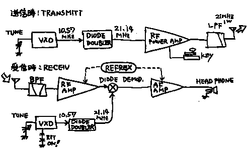
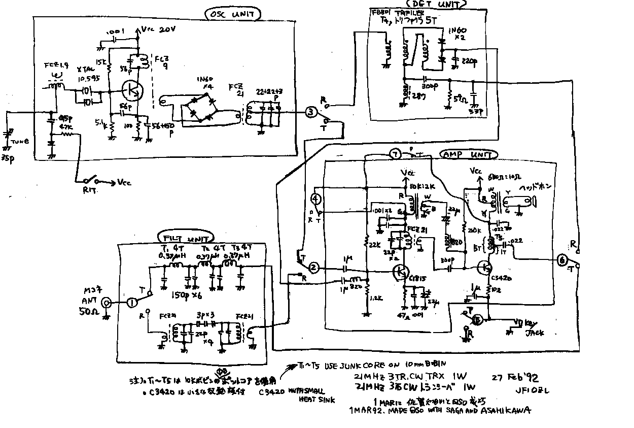
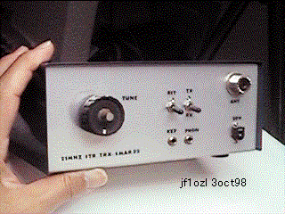
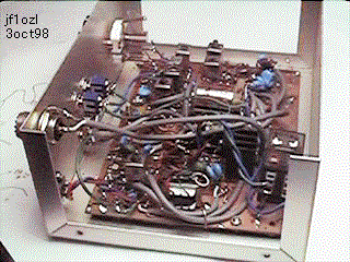
I made CW 1W transceiver with only three transistor. I could make QSO by this machine with Saga, Asahikawa (domestic far distance city),and Indonesia and Taiwan. .. See fig1! Transmitter is three stage. Oscillator makes 10.5MHz signal by VXO oscillator. Diode doubler multiply it to 21MHz signal. Two stage amplifier makes its signal to 1W. The final AMP is keyed. .. Receiver is constructed by a direct conversion type. Antenna signal is amplified with RF-AMP. On the other hand VXO and doubler makes 21MHz beet frequency. The diode-single-balanced-demodulator exchanges the radio frequency-signal to audio-signal. Audio-AMP is constructed by two stage AMP. And the RF and AF AMP is made by reflex construction. I must turn the rit switch, when I receive the signal of DX station. But when I make Zero-tune , I do not need touch it. .. You can see the many T-R switches on the circuit drawing. I used two relays for this purpose..
トランジスター3石式21MHz CW トランシーバー...
CW 1W トランシーバーをたった3 石のトランジスターで作りました.そして、この機械とダイポールアンテナで,佐賀,旭川( 国内の遠い距離の都市) ,およびインドネシア,および台湾と交信できました... fig1 を見て下さい! トランスミッターは,3 段階です.まず、オシレーターは,10.5MHz信号をVXOオシレーターによって発振します.この信号は、ダイオードダブラーによって,21MHz信号になります.2段階の増幅器によって、この信号は1wに増幅されます.終段増幅器のところで,キーイングを行います.受信機は,直接の転換型(ダイレクトコンバージョン)方式です.空中線からの信号は,高周波アンプで増幅されます.その一方で,VXO ,およびダブラーによって,21MHzの信号が作られます.ダイオードシングルバランスド復調器は,無線周波数信号をオーディオシグナルに交換します.オーディオアンプは,2段増幅器によって構成されています.そして,高周波および可聴周波数増幅器は,反射の構造(レフレックス)によって構成されています.交信相手局の信号を受信するときには,リットスイッチをひねらなくてはいけません.しかし,相手の信号にゼロチューンをする時には,それに触る必要はありません.回路図には多くの送受信切り替えスイッチがご覧になれるでしょう。送受信切り替えには2個のリレーを使いました.
3trcw1.gif

3trcw2.gif

3trcwph1.gif

3trcwph2.gif

back to index